
The HX870 was the successor to the Standard Horizon HX851 marine VHF radio. This page was inspired by a collection of information about the HX851 by Paul Sladen. I originally created this page for my own use, then decided it might also be of use to others.
By now the HX870 has a successor as well. Please see the HX890 page created by Robert Elsinga for its technical details.
Several radio users contributed information to this page. Special thanks go to Norm Perron and Christiane Ruetten, who were particularly helpful.
Disclaimer: Modifying the memory image directly using a hex editor is likely not a supported function of the device or its accompanying software. As such, it might void your warranty or brick the radio or even put it into a state where it transmits or receives on frequencies forbidden by international Radio Regulations, local regulations (FCC / BNetzA / …) or local law. Using the radio in such a state might disrupt vital safety-of-life services. Many jurisdictions impose a fine or criminal penalty on it. You should not mess around with any of this stuff unless you know what you’re doing! And, to finally state the obvious: Whatever you do, I cannot be held responsible for it.
Please refer to the documentation written by @cr for the Python software hxtool.
32kB EEPROM, stored by Standard Horizon’s YCE15 software as a *.dat file
You can read and write the radio’s EEPROM using the amazing SHsync Web application. Unfortunately, it requires the Web Serial API, which is currently only natively available on Chrome and Chromium-based browsers.
If you have 010 Editor, you may find the binary template included with the Python software hxtool (originally by @cr) most useful. The hxtool utility also allows reading and writing the radio’s EEPROM on operating systems that can’t run YCE15, such as macOS.
The significance of memory locations marked with a yellow background has not been discovered.
Memory locations marked with a green background appear to have constant values (padding etc.) and can probably safely be ignored.
0xff is used as a generic unused/disabled/padding value for many fields.
Characters are coded as fixed-length ASCII strings (permissible chars include: A-Za-z0-9 &'*,-.:/[]) with 0xff padding, but apparently many strings cannot be used to their full length due to UI limitations.
DSC addresses presently consist of the nine-digit MMSI and a tenth digit, reserved for future use. They are coded with the full ten digits. The last digit is always zero as per Rec. ITU-R M.1080.
| Address | Data | Format |
|---|---|---|
| 0x0000–0x0001 | magic number | 0x0367 = 871 |
| 0x0002–0x0003 | 0x0100 | |
| 0x0004 | multi watch / scan | 0x00=off, 0x01=multi, 0x02=scan |
| 0x0005 | active navigation target | 0x00=none, 0x03=waypoint, 0x04=route |
| 0x0006 | [values seen: 0x00, 0x01, 0x02] | |
| 0x0007 | 0x00 | |
| 0x0008 | selected channel group | |
| 0x0009–0x000a | 0x0e02 | |
| 0x000b | [values seen: 0x00, 0x01, 0x02] | |
| 0x000c | volume setting | numeric (0=min, 15=max) |
| 0x000d | squelch setting | numeric (0=open, 15=max) |
| 0x000e | distress alert status? | usually 0x00 |
| 0x000f | 0x00 | |
| 0x0010–0x0011 | currently selected channel | Channel Index |
| 0x0012–0x0013 | channel used before 16/S was pressed | Channel Index |
| 0x0014 | 0xf0 | |
| 0x0015 | [values seen: 0x01, 0x04] | |
| 0x0016–0x001e | 0xff… | |
| 0x001f | [values seen: 0x00, 0xff] | |
| 0x0020–0x006f | device setup | Setup 1 |
| 0x0070–0x00af | channel group names | 4 * Channel Group Definition |
| 0x00b0–0x00ff | DSC setup | Setup 2 |
| 0x0100–0x0107 | flash ID | AM057N2
|
| 0x0108–0x010e | 0xff… | |
| 0x010f | region selection (group 3 mode) | Region Selection |
| 0x0110–0x0114 | radio last turned off timestamp | 10 nibbles BCD (yymmddhhmm), UTC |
| 0x0115–0x011f | radio last turned off position | Internal Position Format |
| 0x0120–0x012b | channel enabled group 1 | bitmask |
| 0x012c–0x012f | 0x00000000 | |
| 0x0130–0x013f | [values seen: 0x00…, 0xff…] | |
| 0x0140–0x014b | channel enabled group 2 | bitmask |
| 0x014c–0x014f | 0x00000000 | |
| 0x0150–0x015f | [values seen: 0x00…, 0xff…] | |
| 0x0160–0x016b | channel enabled group 3 | bitmask |
| 0x016c–0x016f | 0x00000000 | |
| 0x0170–0x017f | [values seen: 0x00…, 0xff…] | |
| 0x0180–0x0181 | channel enabled group WX | bitmask |
| 0x0182–0x0183 | channel enabled group RG | bitmask |
| 0x0184–0x0186 | channel enabled group EXP | bitmask |
| 0x0187–0x0188 | [values seen: 0x0000, 0xffff] | |
| 0x0189–0x018f | 0xff… | |
| 0x0190–0x019b | scan mem group 1 | bitmask |
| 0x019c–0x01a8 | 0x00… | |
| 0x01a9–0x01ad | [values seen: 0x00…, 0xff…] | |
| 0x01ae–0x01af | 0xffff | |
| 0x01b0–0x01bb | scan mem group 2 | bitmask |
| 0x01bc–0x01c8 | 0x00… | |
| 0x01c9–0x01cd | [values seen: 0x00…, 0xff…] | |
| 0x01ce–0x01cf | 0xffff | |
| 0x01d0–0x01db | scan mem group 3 | bitmask |
| 0x01dc–0x01e8 | 0x00… | |
| 0x01e9–0x01ed | [values seen: 0x00…, 0xff…] | |
| 0x01ee–0x01ef | 0xffff | |
| 0x01f0–0x01f1 | scan mem group WX | bitmask |
| 0x01f2–0x01f3 | scan mem group RG | bitmask |
| 0x01f4–0x01f6 | scan mem group EXP | bitmask |
| 0x01f7–0x01f8 | 0x0000 | |
| 0x01f9–0x01fb | [values seen: 0x00…, 0xff…] | |
| 0x01fc–0x01ff | 0xff… | |
| 0x0200–0x0213 | preset list group 1 | 10 * Channel Index |
| 0x0214 | [values seen: 0x04, 0x07, 0x09, 0xff] | |
| 0x0215–0x021f | 0xff… | |
| 0x0220–0x023f | preset list group 2 | 10 * Channel Index |
| 0x0234 | 0xff | |
| 0x0235–0x023f | 0xff… | |
| 0x0240–0x025f | preset list group 3 | 10 * Channel Index |
| 0x0254 | 0xff | |
| 0x0255–0x025f | 0xff… | |
| 0x0260–0x027f | 0xff… | |
| 0x0280–0x028f | values seen: 0x 8f4e 2daf d24b 6946 708a b496 1980 ffff 0x 9555 3174 d84a ab3b 6e8a 53cf 197e ffff | |
| 0x0290–0x029f | 0xff… | |
| 0x02a0–0x02af | values seen: 0x 1a1a 1a1a 1005 0504 0301 1a05 ffff ffff 0x 0a0f 1419 1f02 0202 0202 0f02 00ff ffff | |
| 0x02b0–0x02bf | 0x0001020305080c141e2b40597090b0ff | |
| 0x02c0–0x02cf | 0x00102030405060708090a0b0c0d0e0f0 | |
| 0x02d0–0x02db | activation per channel group for RG | only 3 least significant bits, one RG channel per byte |
| 0x02dc–0x02df | 0xff… | |
| 0x02e0–0x02f3 | activation per channel group for EXP | only 3 least significant bits, one EXP channel per byte |
| 0x02f4–0x02ff | 0xff… | |
| 0x0300–0x036f | DSC individual call history | 7 * Call History Entry (padded to 16 bytes) |
| 0x0370–0x037f | 0xff… | |
| 0x0380–0x03ef | DSC group call history | 7 * Call History Entry (padded to 16 bytes) |
| 0x03f0–0x03ff | 0xff… | |
| 0x0400–0x046f | DSC position request call history | 7 * Call History Entry (padded to 16 bytes) |
| 0x0470–0x047f | 0xff… | |
| 0x0480–0x04ef | DSC position report call history | 7 * Call History Entry (padded to 16 bytes) |
| 0x04f0–0x04ff | 0xff… | |
| 0x0500–0x057f | DSC polling/test call history | Call History Entry ? |
| 0x0580–0x05a4 | auto polling | 7 DSC addresses (0xff inserted every 3 addr.) ? |
| 0x05a5–0x05df | 0xff… | |
| 0x05e0–0x05e5 | waypoint history | 6 * numeric (one-based index) |
| 0x05e6–0x05ef | 0xff… | |
| 0x05f0–0x05e5 | route history | 6 * numeric (one-based index) |
| 0x05f6–0x05ff | 0xff… | |
| 0x0600–0x077f | channel flags group 1 | 96 * Marine Channel Flags |
| 0x0780–0x08ff | channel flags group 2 | 96 * Marine Channel Flags |
| 0x0900–0x0a7f | channel flags group 3 | 96 * Marine Channel Flags |
| 0x0a80–0x0a9f | 0xff… | |
| 0x0aa0–0x0adf | regional channels | 12 * Private Channel Definition |
| 0x0b00–0x0b57 | expansion channels | 20 * Private Channel Definition |
| 0x0ba0–0x119f | channel names group 1 | 96 * 16 * char |
| 0x11a0–0x179f | 96 * 16 * 0xff | |
| 0x17a0–0x1d9f | channel names group 2 | 96 * 16 * char |
| 0x1da0–0x239f | 96 * 16 * 0xff | |
| 0x23a0–0x299f | channel names group 3 | 96 * 16 * char |
| 0x29a0–0x2f9f | 96 * 16 * 0xff | |
| 0x2fa0–0x305f | channel names group RG | 12 * 16 * char |
| 0x3060–0x311f | 12 * 16 * 0xff | |
| 0x3120–0x325f | channel names group EXP | 20 * 16 * char |
| 0x3260–0x311f | 20 * 16 * 0xff | |
| 0x33a0–0x33bf | 0xff… | |
| 0x33c0–0x345f | channel names group WX | 10 * 16 * char |
| 0x3460–0x34ff | 10 * 16 * 0xff | |
| 0x3500–0x3714 | DSC individual directory: addresses | 100 * 10 nibbles BCD (last nibble zero) after every third address, a single 0xff byte is inserted |
| 0x3715–0x372f | 0xff… | |
| 0x3730–0x3d6f | DSC individual directory: names | 100 * 16 * char |
| 0x3d70–0x3dff | 0xff… | |
| 0x3e00–0x3e6a | DSC group directory: addresses | 20 * 10 nibbles BCD (last nibble zero) after every third address, a single 0xff byte is inserted |
| 0x3e6b–0x3e7f | 0xff… | |
| 0x3e80–0x3fbf | DSC group directory: names | 20 * 16 * char |
| 0x3fc0–0x3fff | 0xff… | |
| 0x4000–0x427f | group monitor setup | 10 * Group Monitor Definition |
| 0x4280–0x42ff | 0xff… | |
| 0x4300–0x5bff | waypoints | 200 * Waypoint Definition |
| 0x5c00–0x5e7f | routes | 20 routes, each with 16 byte name + 16 wpt IDs |
| 0x5e80–0x5eff | 0xff… | |
| 0x5f00–0x649f | DSC log (transmitted calls) | 30 * Call Log Entry |
| 0x64a0–0x64ff | 0xff… | |
| 0x6500–0x77bf | DSC log (received other calls) | 100 * Call Log Entry |
| 0x77c0–0x7ffd | 0xff… | |
| 0x7800–0x7f7f | DSC log (received distress calls) | 40 * Call Log Entry |
| 0x7f80–0x7ffd | 0xff… | |
| 0x7ffe–0x7fff | magic number | 0x0367 = 871 |
There is a bug in the YCE15 software versions 2.0.0.4 and 2.0.1.0 that can cause corruption of the DSC individual directory (likely also other directories) when opening a memory image file containing directory entries that are not alphabetically sorted. However, the bug is only triggered when the “Individual Directory” item is chosen in YCE15. If instead the memory image is directly programmed into the device without first viewing the directory in YCE15, the result is just fine.
Apparently the firmware “knows” whether the radio model is a HX870 or a HX870E independent of the accessible memory content. Non-E models don’t get the region selection menu. However, it would seem logical for this to be defined in software rather than hardware. How does that work? Does perhaps the Windows firmware update software silently modify the firmware based on whether or not an E model is detected before the update (possibly using byte 0x010f)?
An issue seems to sometimes prevent reading values of certain fields from the radio’s memory. This affects memory locations 0x0006, 0x000b–0x000d, 0x0110–0x011f amongst many others. Instead of the true values of those fields, default or padding values appear to be returned. However, locations 0x0010–0x013 and 0x0060 are not affected. While it is not yet clear whether this is an issue with the firmware or YCE15, reading the memory using pyhx870 appears to often yield the true values.
The “activation per channel group” for RG and EXP doesn’t seem to work as I think it should. This ought to be solvable, as the region modes UK and SW contain RG channels that use these activation bits.
| Offset | Data | Format |
|---|---|---|
| 0x0 | status | 0x00=in use, 0xff=not in use |
| 0x1 | channel | numeric 1-based index |
The “channel index” is used to specify individual channels in the memory image. This is simply the position of the respective channel in the channel list of the respective channel group, starting with 1. For example, the “USA” channel group begins with channel 01A, so the number 1 would refer to that channel; number 2 would refer to the next-higher channel, which in “USA” mode is channel 03A; and so on.
Note that none of the default channel lists are fully consecutive. Many have extra channels inserted (for example, Canadian channel 25B is inserted between channels 25 and 26), and for historical reasons, the international channel plan has a big gap before channel 60. Therefore the only way to determine or to resolve channel references is to get a list of all your channels (for example in YCE15 or in the radio itself) and count down from the top, starting with 1 for your first channel. An easy way to do this might be to list all your channels in a spreadsheet application.
“RG” regional and “EXP” expansion channels are appended at the end of the channel list in that order (perhaps “WX” weather channels, too – not sure about these).
I’m not 100 % sure the count matches my data here. The issue appears to be in the upper channels. Does channel 70 maybe not count in the index? How about other "transmission forbidden" channels? Or am I simply counting wrong after all?
The status byte can be used in the preset lists to signal whether that preset is enabled. For other uses of the channel index, it is usually zero.
Sometimes the status byte duplicates the channel byte's value rather than being zero. Different values have also been observed. The significance of this is unclear.
There is some sort of bug in the YCE15 software version 2.0.0.4 that can result in unusable Presets. For example, when setting an “EXP” channel as a preset (possibly also when simply setting a preset to “none”), byte values in the range of 0x81–0xff are set. This results in channels with unusual numbers like “00” or “43” in the radio that give off funny noises when they’re selected.
| Offset | Data | Format |
|---|---|---|
| 0x0 | latitude degrees | 2 nibbles BCD |
| 0x1–0x3 | latitude minutes | 6 nibbles BCD, fixed point (2,4) |
| 0x4 | latitude hemisphere | char (N or S)
|
| 0x5 | padding | higher nibble: 0x0 |
| 0x5–0x6 | longitude degrees | 3 nibbles BCD |
| 0x7–0x9 | longitude minutes | 6 nibbles BCD, fixed point (2,4) |
| 0xa | longitude hemisphere | char (E or W)
|
| Address | Data | Format |
|---|---|---|
| 0x0020–0x0025 | priority channels (per group) | 3 * Channel Index |
| 0x0026–0x002b | sub channels (per group) | 3 * Channel Index |
| 0x002c–0x002f | 0xffffff02 | |
| 0x0030 | display backlight dimmer | numeric (0=off, 5=max) |
| 0x0031 | display contrast | numeric (0=min, 30=max) |
| 0x0032 | key beep volume | numeric (0=off, 5=max) |
| 0x0033 | 0x01 | |
| 0x0034 | multi watch | 0x00=dual, 0x01=triple |
| 0x0035 | 0x01 | |
| 0x0036 | scan type | 0x00=memory, 0x01=priority |
| 0x0037 | scan resume time | numeric (1=min, 5=max) |
| 0x0038 | weather alert | 0x00=off, 0x01=on |
| 0x0039 | 0x00 | |
| 0x003a | emergency LED | 0x00=continuous, 0x01=SOS, 0x02=Blink1, 0x03=Blink2, 0x04=Blink3 |
| 0x003b | water hazard LED | 0x00=off, 0x01=on, 0x02=power-on |
| 0x003c | lamp | 0x00=off, 0x01=3s, 0x02=5s, 0x03=10s, 0x04=continuous, 0x05=20s, 0x06=30s |
| 0x003d | AF pitch CONT | 0x00=normal, 0x01=high-low-cut, 0x02=high-low-boost, 0x03=low-boost, 0x04=high-boost |
| 0x003e | battery save | 0x00=off, 0x01=50%, 0x02=70%, 0x03=80%, 0x04=90% |
| 0x003f | 0xff | |
| 0x0040 | VOX | 0x00=off, 0x01=on |
| 0x0041 | VOX level | numeric (0=min, 4=max) |
| 0x0042 | VOX delay time | 0x00=0.5s, 0x01=1.0s, 0x02=1.5s, 0x03=2.0s, 0x04=3.0s |
| 0x0043 | noise cancel Rx | 0x00=off, 0x01=on |
| 0x0044 | noise cancel Rx level | 0x00=1, 0x01=2, 0x02=3, 0x03=4 |
| 0x0045 | noise cancel Tx | 0x00=off, 0x01=on |
| 0x0046-0x049 | 0x00ffffff | |
| 0x004a | nav display range | 0x00=auto, 0x01=2M, 0x02=5M, 0x03=10M, 0x04=25M |
| 0x004b | nav target waypoint | numeric (one-based index) |
| 0x004c | nav arrival range | 0x00=0.05M, 0x01=0.1M, 0x02=0.2M, 0x03=0.5M, 0x04=1.0M |
| 0x004d | nav routing operation | 0x00=auto, 0x01=manual |
| 0x004e | nav target route | numeric (one-based index) |
| 0x004f | nav target routepoint | numeric (one-based waypoint index) |
| 0x0050 | GPS enabled | 0x00=no, 0x01=yes (when radio is switched on), 0x02=always (even when radio is switched off) |
| 0x0051 | GPS power save | 0x00=off, 0x01=auto, 0x02=50%, 0x03=75%, 0x04=90% |
| 0x0052 | GPS location format | 0x00=ddd°mm′ss″, 0x01=ddd°mm.mm′, 0x02=ddd°mm.mmmm′ |
| 0x0053 | GPS time setup | bitmask; see below |
| 0x0054 | speed units | 0x00=knots, 0x01=mph, 0x02=km/h |
| 0x0055 | distance units | 0x00=nm, 0x01=sm, 0x02=km |
| 0x0056 | altitude units | 0x00=feet, 0x01=metres |
| 0x0057 | GPS pinning | 0x00=no, 0x01=yes |
| 0x0058 | SBAS enabled | 0x00=no, 0x01=yes |
| 0x0059 | map orientation | 0x00=north-up, 0x01=course-up |
| 0x005a | GPS output sentences | bitmask; see below |
| 0x005b | GPS logger interval | 0x00=5s, 0x01=15s, 0x02=30s, 0x03=1min, 0x04=5min |
| 0x005c | 0x00 | |
| 0x005d-0x05f | 0xffffff | |
| 0x0060 | selected soft key page | numeric |
| 0x0061 | soft key timer | 0x01=3s, 0x02=5s, 0x03=7s, 0x04=10s, 0x05=15s |
| 0x0062–0x0064 | soft key page 1 | 3 soft keys; see below |
| 0x0065–0x0067 | soft key page 2 | 3 soft keys; see below |
| 0x0068–0x006a | soft key page 3 | 3 soft keys; see below |
| 0x006b–0x006d | soft key page 4 | 3 soft keys; see below |
| 0x006e–0x006f | 0xffff |
GPS Time Setup
0x80 = 1xxxxxxx = local time (0 = UTC)
0x40 = x1xxxxxx = 24 hour clock (0 = AM/PM)
0x20 = xx1xxxxx = time offset has positive sign (0 = negative sign)
0x1f = xxx11111 = time offset in half hours

Examples:
0x60 = 01100000 = UTC
0xe2 = 11100010 = British Summer Time (UTC +01:00)
0xe4 = 11100100 = Central European Summer Time (UTC +02:00)
0x9e = 10001110 = Pacific Daylight Time AM/PM (UTC -07:00)
GPS Output Sentences
0xc0 = 11xxxxxx - unused
0x20 = xx1xxxxx = DSC/DSE
0x10 = xxx1xxxx = RMC
0x08 = xxxx1xxx = GSV
0x04 = xxxxx1xx = GSA
0x02 = xxxxxx1x = GGA
0x01 = xxxxxxx1 = GLL
| Code | Soft Key |
|---|---|
| 0x00 | none |
| 0x01 | H/M/L transmit power |
| 0x02 | WX / CH |
| 0x03 | SCAN |
| 0x04 | Dual Watch |
| 0x05 | MARK waypoint |
| 0x06 | COMPASS |
| 0x07 | NAVI menu |
| 0x08 | MOB |
| 0x09 | SCAN Memory |
| 0x0a | PRESET |
| 0x0b | STROBE |
| 0x0c | CH NAME |
| 0x0d | LOGGER |
| 0x0e | Noise Cancel |
| Address | Data | Format |
|---|---|---|
| 0x00b0–0x00b4 | own DSC address (MMSI) | 10 nibbles BCD (last nibble zero) |
| 0x00b5 | own DSC address programmed | 0x00=no, 0x01=yes, 0x02=? |
| 0x00b6–0x00ba | own ATIS code | 10 nibbles BCD (or 0xff… if not programmed) |
| 0x00bb | own ATIS code programmed | 0x00=no, 0x01=yes |
| 0x00bc | 0x01 | |
| 0x00bd | DSC Individual call categories | 0x1f (bitmask; see below) |
| 0x00be | DSC All Ships call categories | 0x6f (bitmask; see below) |
| 0x00bf | DSC Group call categories | 0x1f (bitmask; see below) |
| 0x00c0 | DSC Position Request call categories | 0x2f (bitmask; see below) |
| 0x00c1 | DSC Position Report call categories | 0x2f (bitmask; see below) |
| 0x00c2 | DSC Test call categories | 0x2f (bitmask; see below) |
| 0x00c3 | 0x5c | |
| 0x00c4 | DSC Individual Call Reply | bitmask; see below |
| 0x00c5 | DSC beep settings | bitmask; see below |
| 0x00c6 | individual ring | 0x00=5s, 0x01=10s, 0x02=15s, 0x03=20s, 0x04=120s |
| 0x00c7 | 0x04 | |
| 0x00c8 | no act timer | 0x00=1min, 0x01=3min, 0x02=5min, 0x03=10min, 0x04=15min |
| 0x00c9 | CH switch timer | 0x00=off, 0x01=10s, 0x02=30s, 0x03=60s, 0x04=120s |
| 0x00ca | POS fix wait | 0x00=15s, 0x01=30s, 0x02=60s, 0x03=90s, 0x04=120s |
| 0x00cb–0x00cf | 0xff01ff0000 | |
| 0x00d0–0x00df | 0xff… | |
| 0x00e0 | auto POS polling activation | 0x00=stop, 0x01=start |
| 0x00e1 | auto POS polling type | 0x00=request, 0x01=report |
| 0x00e2 | auto POS time | 0x00=30s, 0x01=1min, 0x02=2min, 0x03=3min, 0x04=5min |
| 0x00e3–0x00e4 | 0x0200 | |
| 0x00e5–0x00e6 | [values seen: 0x4630, 0x8cff] | |
| 0x00e7–0x00ef | 0xff… | |
| 0x00f0–0x00f1 | 0x0002 | |
| 0x00f2 | GM interval | 0x00=1min, 0x01=3min, 0x02=5min, 0x03=10min, 0x04=15min |
| 0x00f3 | [values seen: 0x01, 0x03, 0xff] | |
| 0x00f4 | 0x00 | |
| 0x00f5–0x00f6 | [values seen: 0x4630, 0x8cff] | |
| 0x00f7–0x00ff | 0xff… |
DSC Call Categories
0x80 = 1xxxxxxx = Distress
0x40 = x1xxxxxx = Urgency
0x20 = xx1xxxxx = Safety
0x10 = xxx1xxxx = Routine
0x0f = xxxx1111 - Hi/Low Tx power on channel 70 by category?
Note: The DSC call categories (priorities) are prescribed by Rec. ITU-R M.493. The HX870 by default correctly implements the category options for class D radios, except that the HX870 additionally allows position request and polling calls.
DSC Individual Call Reply
0x80 = 1xxxxxxx = automatic reply
0x40 = x1xxxxxx = reply 'able'
other bits: unknown

Values seen:
0x38 = 00111000 = automatic 'unable' reply disabled
0x78 = 01111000 = automatic 'able' reply disabled
0xb8 = 10111000 = automatic 'unable' reply enabled
0xf8 = 11111000 = automatic 'able' reply enabled
DSC Beep Settings
0x80 = 1xxxxxxx = Individual
0x40 = x1xxxxxx = All Ships
0x20 = xx1xxxxx = Group
0x10 = xxx1xxxx = Position Request
0x08 = xxxx1xxx = Position Report
0x04 = xxxxx1xx = Geographic
0x02 = xxxxxx1x = Polling
0x01 = xxxxxxx1 = Test Call

Default value:
0xec = 11101100 = always, except for POS requests, polling, and test calls
| Address | Data | Format |
|---|---|---|
| 0x010f | HX870E: selection of the region for channel group 3 | region code; see below |
| HX870: region selection not supported | 0xff |
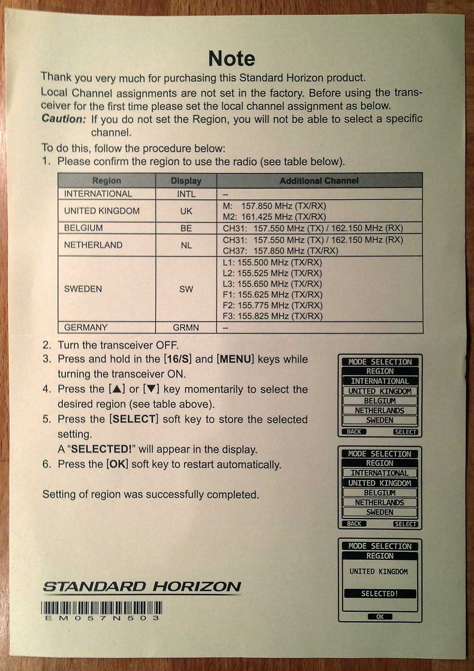
HX870E radios are usually distributed with a leaflet in the packaging explaining how to set a region. The HX870 model (non-E) is apparently hard-coded to only support Canada as a region.
The region can be selected by holding down MENU and 16/S while turning on the HX870E. The menu described in the leaflet will then appear. Selecting a region will primarily affect channel group 3 and the regional (RG) channels, resetting channel flags and names to whatever the factory settings are for the selected region. The following group 3 regional modes are available for the HX870E:
| Code | Region | Region (menu name) | Channel Group 3 Name | Channels in Group 3 | Regional Channels |
|---|---|---|---|---|---|
| 0x00 | Canada | INTERNATIONAL | CAN | Canadian | — |
| 0x01 | British Isles | UNITED KINGDOM | UK | international | M, M2 |
| 0x02 | North Sea (Belgium) | BELGIUM | BE | international + 31 | — |
| 0x03 | North Sea (The Netherlands) | NETHERLAND | NL | international + 31, 37 | — |
| 0x04 | Northern Europe | SWEDEN | SW | international | L1, L2, L3, F1, F2, F3 |
| 0x05 | European inland waterways | GERMANY | GRMN | RAINWAT | — |
Some of the region names Standard Horizon use in the menu are confusing to say the least. For example, a vessel sailing the German Baltic coast would need an international channel plan. It might seem logical to select “INTERNATIONAL” or “GERMANY” as regional mode, but neither one of those would yield an international channel plan in group 3. Instead, you would want to either use the “INTL” channel group 2, which isn’t affected by the regional mode setting at all, or “SWEDEN” mode for channel group 3, which has the benefit of enabling the Danish leisure channels.
Notably, “NETHERLAND” mode provides an international channel plan even though the extra channels are mostly useful in Dutch inland waterways, where RAINWAT applies. This looks like a firmware bug.
| Offset | Data | Format |
|---|---|---|
| 0x0 | channel group enabled | 0x00=no, 0x01=yes |
| 0x1 | DSC enabled | 0x00=no, 0x01=yes |
| 0x2 | ATIS enabled | 0x00=no, 0x01=yes (see note below) |
| 0x3–0x6 | channel group name | 0–4 chars, 0xff padded |
| 0x7 | 0xff | |
| 0x8–0xf | model string? | 5–6 chars, 0xff padded |
Only the first three channel groups are in fact available for use. YCE15 uses the “ATIS enabled” field of the fourth channel group definition (memory location 0x00a2) to decide whether or not to display the ATIS setup (0x00=no, 0x01=yes).
| Offset | Data | Format |
|---|---|---|
| 0x0–0x4 | DSC address (MMSI) | 10 nibbles BCD (last nibble zero) |
| 0x5 | call type / priority ? | |
| 0x6–0x7 | channel used (individual/group call only) | Channel Index (or 0xffff) |
The entries are listed in descending order of age (oldest first).
The presumed “call type” or “priority” field is usually 0x03 for individual/group calls and 0x02 for position request/report calls. Polling and test call histories appear to either share the same memory area; it’s not yet clear whether they are differentiated by the “call type”/“priority” field, or whether there are columns in this area (left column polling, right column test).
It is not known why the channel is recorded in the history in addition to the log.
| Offset | Data | Format |
|---|---|---|
| 0x0 | channel ID | numeric |
| 0x1-0x2 | flags | bitmask; see below |
| 0x3 | padding/reserved? | 0xff |
0x8000 = 1xxxxxxx xxxxxxxx = frq shift Rx only
0x4000 = x1xxxxxx xxxxxxxx = frq shift Rx and Tx
0x2000 = xx1xxxxx xxxxxxxx = high power allowed
0x1000 = xxx1xxxx xxxxxxxx = Tx allowed
0x0800 = xxxx1xxx xxxxxxxx = high power allowed, but low power is default
0x0400 = xxxxx1xx xxxxxxxx - unused?
0x0200 = xxxxxx1x xxxxxxxx = channel suffix: "B"
0x0100 = xxxxxxx1 xxxxxxxx = channel suffix: "A"
0x0080 = xxxxxxxx 1xxxxxxx = DSC ship/ship channel
0x007f = xxxxxxxx x1111111 = channel prefix: 0x7f=none, other=numeric

Frequent combinations:
0x30ff = 00110000 11111111 = DSC ship/ship simplex channel
0x10ff = 00010000 11111111 = DSC ship/ship simplex channel, limited to 1W
0x18ff = 00011000 11111111 = DSC ship/ship simplex channel, defaults to 1W
0x307f = 00110000 01111111 = other simplex channel
0x107f = 00010000 01111111 = other simplex channel, limited to 1W
0x300a = 00110000 00001010 = other simplex "10" channel
0x7014 = 01110000 00010100 = other simplex "20" channel
0x317f = 00110001 01111111 = USA "A" channel
0x827f = 10000010 01111111 = CAN "B" channel
0xb07f = 10110000 01111111 = duplex channel
0x907f = 10010000 01111111 = duplex channel, limited to 1W
0x007f = 00000000 01111111 = Tx forbidden

Some other useful combinations:
0x807f = 10000000 01111111 = duplex channel, Tx forbidden
0x987f = 10011000 01111111 = duplex channel, defaults to 1W
0x187f = 00011000 01111111 = simplex channel, defaults to 1W
0x197f = 00011001 01111111 = simplex "A" channel, defaults to 1W
0x5a7f = 01011010 01111111 = simplex "B" channel, defaults to 1W
0x180a = 00011000 00001010 = simplex "10" channel, defaults to 1W
0x5814 = 01011000 00010100 = simplex "20" channel, defaults to 1W
0x4014 = 01000000 00010100 = simplex "20" channel, Tx forbidden
DSC ship/ship channels (also known as “ship to ship” or “intership” channels) are those channels that the radio offers to choose from e. g. when initiating a DSC individual call. Any channel can be added or removed from that list simply by setting or clearing its “ship/ship” flag in the bitmask described above. An arbitrary channel can also be chosen for a DSC call after pressing the “manual” soft key, but customizing the list of ship/ship channels may be useful to streamline routine operation.
Firmware 2.03 appears to have a bug in the “GRMN” (RAINWAT) channel group: Channel 20 doesn't have the “high power allowed” bit set although high power is allowed. This is easily fixable by modifying memory location 0x0955 in the memory image from 0x90 to 0xb0.
Firmware 2.03 also appears to set the “suffix A” bit for channel 88, but not for 87 for the USA channel group. Given that both channels were redefined at the same time for the introduction of AIS, it’s clear that either both or none should have the “A”. According to the manual, both should have the suffix, but according to the Coast Guard, neither should have it.
Firmware 2.03 appears to have an additional bug in the “INTL” channel group (possibly others as well): Channels 15 and 17 are no longer a guard band for channel 16 as per ITU RR (App. 18) and Rec. M.1084. Transmitting with full power is allowed on these channels unless they’re used for internal on-board communication. It would appear to make sense to at least code these as “low power default” if not “unrestricted power”.
| Offset | Data | Format |
|---|---|---|
| 0x0–0x1 | channel ID | 2 * char (lower case not supported) |
| 0x2–0x4 | Rx frequency | 5 nibbles BCD (in kHz above 100 MHz) |
| 0x4 | padding? | lower nibble: 0x0 |
| 0x5–0x7 | Tx frequency | 5 nibbles BCD (in kHz above 100 MHz) 0xfffff = Tx forbidden |
| 0x7 | channel definition flags | lower nibble: bitmask; see below |
0x08 = xxxx1xxx = low power
0x04 = xxxxx1xx - ?
0x02 = xxxxxx1x - ?
0x01 = xxxxxxx1 = user power up

Frequent combinations:
0x00 = xxxx0000 = standard
0x08 = xxxx1000 = limited to 1W
0x09 = xxxx1001 = defaults to 1W
0x06 = xxxx0110 = ?

Illegal combinations:
0x0a = xxxx1010
0x0b = xxxx1011
0x0c = xxxx1100
0x0d = xxxx1101
0x0e = xxxx1110
| Offset | Data | Format |
|---|---|---|
| 0x00–0x04 | GMID | 10 nibbles BCD (last nibble zero) |
| 0x05–0x0f | GM name | |
| 0x10–0x3f | member addresses | 9 * 10 nibbles BCD (last nibble zero) after every third address, a single 0xff byte is inserted |
| Offset | Data | Format |
|---|---|---|
| 0x00–0x04 | MMSI from pos report | 10 nibbles BCD (last nibble zero) |
| 0x05–0x0f | waypoint position | Internal Position Format |
| 0x10–0x1e | waypoint name | 15 * char |
| 0x1f | waypoint id | numeric (one-based) |
Waypoints created on the device from any source other than a DSC position report have the usual 0xff… placeholder in the MMSI field, except that the last nibble is 0x0. This looks like a firmware bug.
| Offset | Data | Format |
|---|---|---|
| 0x00 | message read flag | 0x00=read, 0x80=unread |
| 0x01–0x06 | call timestamp | 12 nibbles BCD (yyyymmddhhmm), UTC |
| 0x07–0x08 | DSC call type | BCD-coded service command code; see below |
| 0x09–0x0d | DSC address (MMSI) | 10 nibbles BCD (last nibble zero) |
| 0x0e–0x0f | 0xffff | |
| 0x10–0x11 | DSC category | BCD-coded service command code; see below |
| 0x12–0x13 | DSC message 1 | BCD-coded service command code; see below |
| 0x14–0x15 | DSC message 2 | BCD-coded service command code; see below |
| 0x16–0x18 | DSC frequency or channel info | BCD-coded; see below |
| 0x19–0x1e | 0xff… | |
| 0x1f | [values seen: 0x01, 0x40, 0x41, 0xff] | |
| 0x20–0x21 | position timestamp | 4 nibbles BCD (hhmm), UTC |
| 0x22–0x2c | position (if applicable) | Internal Position Format |
| 0x2d | 0xff | |
| 0x2e–0x2f | DSC end of sequence | BCD-coded service command code; see below |
DSC Call Type
0x0112 = Distress
0x0114 = Group
0x0116 = All ships
0x0120 = Individual
DSC Category
0x0100 = Routine
0x0108 = Safety
0x0110 = Urgency
0x0112 = Distress
DSC Message 1
For calls of type “Distress”: Nature of distress
0x0100 = Fire, explosion
0x0101 = Flooding
0x0102 = Collision
0x0103 = Grounding
0x0104 = Listing, in danger of capsizing
0x0105 = Sinking
0x0106 = Disabled and adrift
0x0107 = Undesignated distress [default value]
0x0108 = Abandoning ship
0x0109 = Piracy / armed robbery attack
0x0110 = Man overboard
0x0112 = VHF EPIRB Emission

For other call types: First telecommand
0x0100 = F3E/G3E all modes telephony
0x0101 = F3E/G3E duplex telephony
0x0103 = Polling
0x0104 = Unable to comply
0x0110 = Distress acknowledgement
0x0112 = Distress alert relay
0x0118 = Test
0x0121 = Ship position or location registration updating
0x0126 = No information [default value]
DSC Message 2
For calls of type “Distress”: Subsequent communication mode
0x0100 = F3E/G3E all modes telephony [default value]

For other call types: Second telecommand
0x0100 = No reason given
0x0126 = No information [default value]
DSC Frequency or Channel Information
0x90____ = last four nibbles represent the VHF channel, coded as BCD
0xffffff = no information
DSC End Of Sequence
0x0117 = individual call requiring acknowledgement
0x0122 = answer to call that required acknowledgement
0x0127 = other call
Reference: Rec. ITU-R M.493, section 8 “Messages” and table A1-3 “Use of symbol Nos. 100 to 127”
